-40%
WB D1G1-DIY Wideband Air Fuel Ratio Controller Kit - No Sensor
$ 27.26
- Description
- Size Guide
Description
WB WIDEBANDWB D1-DIY Wideband Controller Board
Free Shipping
WIDE-BAND.com since 2011
WB D1-DIY Digital Wideband Controller, G1 LED Display, Plastic Enclosure and Harness
- - - - - - - - - - - - - - - - - - - - - - - - - - - - - - - - - -
YOU CAN USE APSX G1 LED DISPLAY OR A PC VIA APSX SOFTWARE WITH DIGITAL OUTPUT TO READ AFR. OTHER BRAND AFR GAUGES WOULD NOT WORK.
Box content:
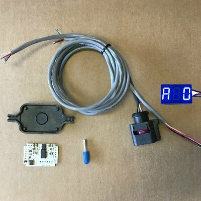
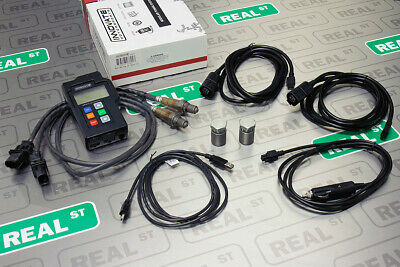
D1 wideband controller board, G1 LED Display (Blue, Red, White, Green, or Orange) and plastic enclosure for potting with epoxy and harness.
WIDEBAND O2 SENSOR IS NOT INCLUDED.
Item Description:
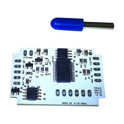
It is only 1.50” and 0.90” size and much more cost effective than any other wideband controller in the market today.
Item Specifications:
It comes with ONLY the wideband controller board, plastic enclosure, G1 LED display and power and output cables. New D1 is only 1.50” and 0.90” in size (1/5 of a credit card size) and much more cost effective than any other wideband controller in the market today. It is also sold with weather and temperature proof if the enclosure is filled with epoxy.
D1-DIY wideband controller gauge features:
1 – Simple guidelines for an easy installation
2 – Four types of fuel (E85, Diesel, Gasoline, Methanol) and lambda options
3 – WB G1 LED AFR display and to an EMS module
4 - Multiple outputs for digital (to PC), analog (to data logger / EMS), narrowband for simulation and extra switch options
5 - No need a PC or tablet for programming upper/lower limits and other settings
6 – Comes with a magnet sensor that replaces the “button” for programming. Instead of pushing a button, a magnet works in a very convenient and innovative way.
OUTPUTS
1 – Analog 0-5V (9=19 AFR) linear output for engine management systems (EMS) and data loggers (MegaSquirt)
2 – Digital output is 9600 8N1 serial that can be connected to your PC
3 – Simulated NB output
WIRING
Positive power cable goes to 12V source in your vehicle. Ground power cable goes to a grounded source such as battery ground (-) post.
Green digital output is 9600 8N1 serial that can be connected to your PC. If you want to connect other devices such as data loggers or AFR gauges, you can use white analog cable for 0-5V output. Brown narrowband cable is for simulated NB.
GUIDELINE FOR THE LOCATION OF THE OXYGEN SENSOR
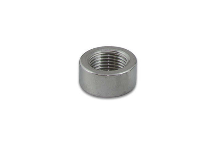
Weld the bung at least 24” downstream of exhaust port outlet or 24” after the turbocharger. It should always be before the Catalytic Converter. Also it should be before the X or H pipe if there is. Bung should be welded on the upper section which is located between 10AM or 2AM clock positions. Please check your vehicle for exhaust leaks, camshaft overlap and open exhausts because those would cause false lean readings. Not following these directions may result in premature failure of the sensor.
Shipping
Returns
Disclaimer
Shipping
Returns
Disclaimer
We offer FREE shipping on all orders!
Your order will be shipped within 2 working days of receiving payment (Monday-Friday) and you should expect to receive it two or five days after shipment.
APSX WIDEBAND DOES NOT warrants this product as it is quality checked before it is shipped. Due to the nature of the product, the customer is responsible to have enough expertise on how to connect and operate based on the guidelines provided.
APSX WIDEBAND shall not be liable for direct, special, incidental, or consequential damages resulting from any legal theory including, but not limited to, lost profits, downtime, goodwill, damage, injury to persons, or replacement of equipment and property due to improper installation, integration and/or misuse of any APSX WIDEBAND’s product(s). This warranty applies to the original purchaser of product and is non-transferable. All implied warranties shall be limited in duration to the said 90 day warranty period.
TERMS OF USE
APSX WIDEBAND does not guarantee the product functionality with any ECU, data logger or other devices that uses the output signals. Implementation and integration of the product with any other device(s) must be done at your own risk. Improper installation and usage may lead to engine damage. Mount and install the product in a location where it does not obstruct the driver’s view and/or ability to safely control the vehicle.
Click here to see description
APSX WIDEBAND
APSX D1-DIY Wideband Controller Board
Free Shipping
WIDE-BAND.com since 2011
APSX D1 Digital Wideband Controller (Board ONLY) 1/5 of a credit card size
- - - - - - - - - - - - - - - - - - - - - - - - - - - - - - - - - -
Item Description:
It is only 1.50” and 0.90” size and much more cost effective than any other wideband controller in the market today.
Item Specifications:
We do not suggest buying this DIY board before using APSX D1 Controller with success.
We can not provide extensive support to this product since it requires fundamental serial port communication and electronics knowledge.It is smaller and more cost effective than other leading brands in the market today. It comes with ONLY the wideband controller board. O2 sensor, sensor connector, power and output cables are sold separately. New D1 is only 1.50” and 0.90” in size (1/5 of a credit card size) and much more cost effective than any other wideband controller in the market today. It is also sold with weather and temperature proof enclosure and wiring, if needed.
D1-DIY wideband controller gauge features:
1 – Simple guidelines for an easy installation
2 – Four types of fuel (E85, Diesel, Gasoline, Methanol) and lambda options
3 – Ready to install with APSX G1 LED AFR display and to an EMS module
4 - Multiple outputs for digital (to PC), analog (to data logger / EMS), narrowband for simulation and extra switch options
5 - No need a PC or tablet for programming upper/lower limits and other settings
6 – Comes with a magnet sensor that replaces the “button” for programming. Instead of pushing a button, a magnet works in a very convenient and innovative way.
OUTPUTS
1 – Analog 0-5V (9=19 AFR) linear output for engine management systems (EMS) and data loggers (MegaSquirt)
2 – Digital output is 9600 8N1 serial that can be connected to your PC
3 – Simulated NB output
WIRING
APSX D1 can be connected to oxygen sensor cable (5 cables) and five output wires as shown in the picture above. Wires are sold at wide-band.com if needed. The free data output APSX software can be dowloaded from wide-band.com as well.
If you purchase a kit with D1, it will arrive assembled and in an weather and temperature proof enclosure filled with epoxy. Positive power cable goes to 12V source in your vehicle. Ground power cable goes to a grounded source such as battery ground (-) post.
Green digital output is 9600 8N1 serial that can be connected to your PC. If you want to connect other devices such as data loggers or AFR gauges, you can use white analog cable for 0-5V output. Brown narrowband cable is for simulated NB.
GUIDELINE FOR THE LOCATION OF THE OXYGEN SENSOR
Weld the bung at least 24” downstream of exhaust port outlet or 24” after the turbocharger. It should always be before the Catalytic Converter. Also it should be before the X or H pipe if there is. Bung should be welded on the upper section which is located between 10AM or 2AM clock positions. Please check your vehicle for exhaust leaks, camshaft overlap and open exhausts because those would cause false lean readings. Not following these directions may result in premature failure of the sensor.
In The Box:
APSX D1-DIY board and magnet.
Shipping
We offer FREE shipping on all orders!
Your order will be shipped within 2 working days of receiving payment (Monday-Friday) and you should expect to receive it two or five days after shipment.
Returns
APSX WIDEBAND DOES NOT warrants this product as it is quality checked before it is shipped. Due to the nature of the product, the customer is responsible to have enough expertise on how to connect and operate based on the guidelines provided.
Disclaimer
APSX WIDEBAND shall not be liable for direct, special, incidental, or consequential damages resulting from any legal theory including, but not limited to, lost profits, downtime, goodwill, damage, injury to persons, or replacement of equipment and property due to improper installation, integration and/or misuse of any APSX WIDEBAND’s product(s). This warranty applies to the original purchaser of product and is non-transferable. All implied warranties shall be limited in duration to the said 90 day warranty period.
TERMS OF USE
APSX WIDEBAND does not guarantee the product functionality with any ECU, data logger or other devices that uses the output signals. Implementation and integration of the product with any other device(s) must be done at your own risk. Improper installation and usage may lead to engine damage. Mount and install the product in a location where it does not obstruct the driver’s view and/or ability to safely control the vehicle.
